"So let's ride and ride and ride and ride
Singin' la la la la la la la la"
- Iggy Pop
The TrackJoint, along with the trax library, was developed by us [1]
to rail trains in a physical simulation like NVIDIA PhysX. The challenge here
is to restrict the movements of the wheel frames of a train relative to a
track system without losing the reality of the whole simulation or risking
problems of instability. Moreover, we wanted to achieve effects like outer
forces such as gravity or collisions acting realistically on trains. The
solution was to implement the connection between the wheel frame and track in
the same way that built-in joints like rotational or spherical joints are
working. The result of this effort was the TrackJoint
[2].
We created a C++ extension for NVIDIA Omniverse called railOmniverse
[3], which includes the TrackJoint
along with some additional tools for creating track systems and a motor model
together with brake and (wheel) friction.
Now, we are considering further development to bring more functionality from the trax library to the railOmniverse extension. We aim to provide a high-level overview of the functionality the trax library has to offer in this blog article. It is written from a developer's perspective and serves as a condensed version of what we refer to as the 'trax book' [4].
dim and spat are two compact libraries we developed. They are utilized by the trax library and can be used independently, both from each other and from the trax library itself. 'dim' provides dimensions and units for stark-naked numbers (for tranquility of mind we call the latter 'values'). With it, you can write:
            Mass m = 60.4_kg;
            Mass m2 = 60_kg + 400_g;
            Mass m3 = m1 + m2;
            assert( Equals( m3, 120.8_kg, 1_g ) );
            Vector<One> Ez = {0,0,1};
            Vector<Acceleration> a = 9.81_mIs2 * -Ez;
            Vector<Force> F = m * a;
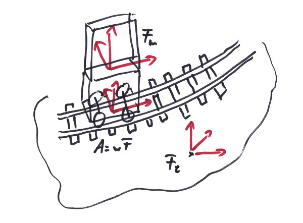
Frame that
looks like the 'F's in the above picture:
            Frame<Length,One> pose;
            pose.P = {10_m,0_m,0_m};
            pose.T = {1,0,0};
            pose.N = {0,1,0};
            pose.B = {0,0,1};
A track is a segment of a Curve with a strong idea about what is 'up' and
two ends that can each be coupled to one of another track's ends. The track is
parameterized by its arc length, denoted as s. In a process referred to as a
transition, the parameter s is mapped to a pose in the
Frame<Length,One> format, providing
position and orientation in world space. Switches essentially act as
reconnectors for adjacent track ends:

A Location object is employed to facilitate
the transition of an entire track system. It manages the crossover between
coupled tracks, their respective parametrizations, and offers simple
Location::Move( Length ds ) methods
for traversing along the tracks. Additionally, it serves as the mechanism to
trigger Sensors and receive
Signals (see below).
Any track in the wild can be described by a
Curve and a
Twist. The
Curve shape defines the inner geometry,
while the Twist determines the
Up direction. With an additional
Frame<Length,One>, the 3D pose of
the entire track is determined. Collectively, these three entities
are referred to as the total geometry of the track.
Interestingly, there exists a mathematical theory known as 'Curve Theory',
initially formulated by French mathematicians Monsieur Frenet and Monsieur
Serret about 160 years ago. This theory conveniently describes curves in terms
of curvature and torsion, representing velocities while moving along them.
This is the very reason why the TrackJoint
can be elegantly formulated for a velocity or momentum-based physics engine
like NVIDIA PhysX.
The trax library offers a variety of stock curves and methods for creating
adaptive curves such as Splines from
sampled data. Twists for most use cases
are also provided.
The tracks come with a reservation system that can be utilized for managing occupied areas.
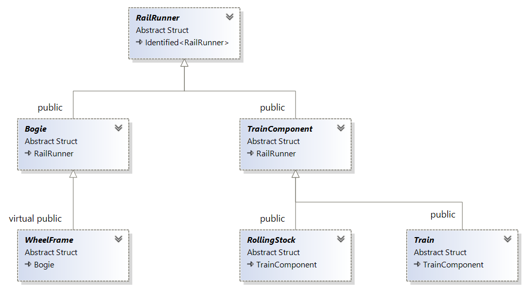
A Bogie is a physical body able to run along a track. We refer to
this as a RailRunner (see below). It can take the form of a
WheelFrame, equipped with a
TrackJoint (having wheels) to
adhere to a track. Alternatively, it may be connected to other
Bogies or
WheelFrame
by hinges. While it's possible to use a
TrackJoint directly, it comes with
a relatively simple drive. To represent wheels and leverage a motor
model, the Bogie and
WheelFrame interfaces are introduced.
The motor model relies on a Tracktion Force Characteristic,
which can be defined for each WheelFrame.
This establishes a relationship between velocity and the fraction of
maximal motor force that can be applied at a specific velocity:
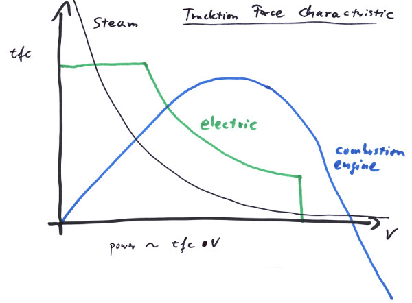
Many motors are inherently unable to maintain their traction forces independently of the already reached velocity, owing to the construction of the motor and additional gears. Regardless of the type of engine and gear system, a well-defined TFC ensures correct behavior concerning maximum speed, available power output, and tractive effort.
The WheelFrame also includes models
for brakes and wheel-related friction. A
RollingStock interface is provided to
encapsulate a group of hinged Bogies,
especially in complex configurations such as passenger wagons connected
by Jacobs bogies.
A RollingStock is a managment class for a group of hinged Bogies. It can act as train component.
A Train consists of one or more
TrainComponents that are coupled together
as a chain. The Train itself is
considered a TrainComponent:
Railroad companies treat a single locomotive or wagon on a journey as a train. Trains can also be seen as constituted from two or more subtrains. While this is often semantic, and coupled rolling stocks or bogies behave correctly without being explicitly recognized as a train, it has proven useful to have a train object to handle such configurations as a whole. This includes steering all locomotives at once, deploying all brakes, or re-rail an entire train.
In railroading, numerous hard-wired logical connections are essential. For instance, lanterns along the track indicate the state of the switches. Another application involves sensors in the track that detect a wheelset passing over them (see below).

A Plug is inserted into a
Jack to receive the
Jack's pulses. Typically, each
Plug is very specific; for example, one
might switch on a building's light. The Jack
is also specific, perhaps part of a sensor detecting environmental light
levels and triggering a pulse if it falls below a certain threshold. Then a
simple decision to plug these two sockets together would turn on the light in the
appropriate moment.
To avoid placing redundant sensors for multiple lamps, a
Plug can have its own
Jack to insert another
Plug:

In railway applications, a switch may have two possible states: 'go,' indicating the straight line, and 'branch,' indicating the diverting route. Here, we provide Jacks n' Plugs to either trigger the switch to those settings (PlugTo) or trigger something else if the switch is set by what cause soever (JackOn):
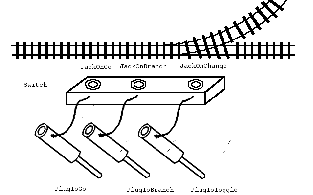
The first application might be to connect it with a lamp showing the switches status:

This way, the semaphore always displays the actual switch status,
and a change in the semaphore triggers the switch. Many trax entities
offer such Plugs and
Jacks for their discrete settings.
Every Plug is compatible with every
Jack, providing endless combinations to
explore.
A Sensor along a track detects the event of something passing by in
its direction. These sensors have various applications; for instance,
they can trigger each time a wheelset passes, incrementing a counter.
Other Sensors can trigger when a wheelset exits a
designated area, decrementing the counter. This mechanism is commonly
used to lower a barrier when the counter is greater than zero and raise
it when it returns to zero. This provides protection for a road crossing
multiple track lines, even if trains become disconnected.
Other applications involve sensing a train's front or end passing the
Sensor's location. The
Sensor can be configured to trigger
only under specific circumstances, such as when the velocity is outside
a certain range. While it might be tempting to have the
TrackJoint (see above) trigger
Sensors along its journey, it is usually
more useful to start with a more general notion of 'something', like a
WheelFrame carrying a
Location to relay an
Event and trigger the
Sensor:
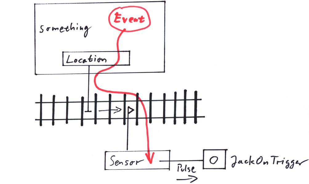
As a Location moves along the tracks,
representing, for example, a train tip, it is fed an
Event, containing the necessary
information for a specialized Sensor
to determine whether to trigger. If the Sensor
triggers, it creates a pulse in an associated Jack
(see above).
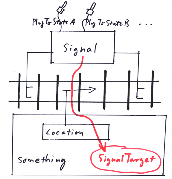
A Signal is a directed range along the tracks that conveys information
to be sent to a SignalTarget as a
Location moves within that range, following
its direction. This mechanism aligns with modern 'Linienzugbeeinflussung'
[5], where time-varying information is sent to a train along
a track range. It also applies to traditional signaling, considering the
range between a pre-signal and a main signal. In this scenario, the train
conductor is expected to interpret the signal's meaning within the range and
act accordingly — such as stopping in front of the main signal after passing
the pre-signal. Once the train passes the main signal, its state no
longer applies:
'Punktförmige Zugbeeinflussung' [6] is only
slightly more intricate, requiring a non-zero range long enough to
prevent the Location from jumping
over it in a single simulation step, considering the maximum expected speed.
Trend Verlag, Leo-Wohleb-Str. 8 · D-79098 Freiburg
Marc-Michael Horstmann
horstmann.marc@trendverlag.de

TrackJoint